Before getting into the detail, some context...
When I designed and built the pre-amp board, I didn't know which module I'd use, so the Bluetooth provision had to be "generic". As such, the pre-amp interface simply carries 5V, which is switched on and off by the PIC, and picks up the audio and a "connected" signal, which ends up at the PIC. It also carries across both signal and power grounds.
I was worried about this last point, as these cheap modules only have a single ground. I knew that simply joining the two earths at the Bluetooth module would upset the carefully constructed grounding arrangements, causing noise and an increase in the measured distortion. But I didn't want the current taken by the Bluetooth module finding its way into the signal ground, so a power ground was essential. Although I was a long way away from seriously getting into all this, I knew from reading around the forums that I wouldn't be the first person to grapple with digital noise from these modules!
Physically, I planned to mount the module somewhere in the case away from the metalwork and electronics. These modules generally don't have holes for fixing screws, so it looked like resorting to double-sided foam tape or cable ties - not ideal. Once the position of the pre-amp board on the rear panel had been decided, I cut down a scrap of plywood and screwed it to one of the side supports, which gave me a place to attach the module that resulted in it being held near the top of the case. I assumed that I'd simply wire it straight to the Molex connector on the pre-amp board. But all that changed when I got into the detail!
Contents
The KRC-86B Bluetooth module
After a bit of research I settled on the KRC-86B. It's available for around £8, so it is by no means the cheapest, but still incredible value. This module is frequently recommended on the vintage radio forums for Bluetooth conversions for 2 main reasons:
- It contains an analogue switch which allows for automatic switching between the Bluetooth device and a local source of audio
- When connecting, it does not make any extrenuous noises. Many modules chime or beep when connecting, which gets pretty annoying!
For this project, this first point isn't relevant as I'm switching the audio separately, but you can see how this could be handy for a retro-fit - assuming you don't mind the current the module takes when not connected, which could be a problem for battery gear. However, the second reason is an important point.
Important: This article discusses version 4.0 of the module. Be aware that there is now a version 4.2 available, and it does look to have a number of differences. I'm tempted to pick up a couple to see exactly what's changed - if so, I'll post an addendum here. But for now, please be aware that what follows might not apply directly to your module.
This module uses a CSR8630, originally from CSR (Cambridge Silicon Radio), now Qualcomm. It is quite an old product that is not recommended for new designs, which might explain why it's so ubquitous in these cheap modules. It supports Bluetooth version 4, which is more than adequate for this project.
The module runs from 5V, and consumes around 30mA when connected. The audio output level measures 0.83VRMS when fed with 0dBFS.
A 470uF capacitor and a blue LED are supplied with the module. Although no instructions are included, it's obvious that the cap is intended to be connected across the supply input. Without it, there is a lot of digital noise on the audio outputs. With it, it's much better, but still a bit on the high side, especially if your Bluetooth device is not set to maximum volume.
I mentioned noise in the introduction because it's a common issue with these sorts of modules, caused by the shared power and signal grounds. Many recommend using brute-force measures such as isolated DC-DC converters or audio transformers. Suffice to say, I solved the problem without recourse to these expensive and/or inconvient approaches, as explained later. It's also worth saying that the exact level of noise experienced depends strongly on the exact scenario, including how you derive the 5V supply for it, so if you're lucky, you might well be happy with the results with no modifications.
The LED has dedicated connections, and is used to indicate the connection state; flashing slowly when powered but not connected, and lighting steadily when a connection has been established. Its use is optional, but it's worth saying that it adds about 1mA to the current draw. As it's rather bright, an additional series resistor to supplement the 470Ω on the module might be a good plan.
In addition to this, there is an "EN" output, which is high (3V3) when connected and grounded when not. This allows you to integrate the module with a control system in a more complex project, as we do here.
Physically, the module measures about 30mm square, with the bulk of the connections presented along one edge. These are spaced at 2mm rather than a Veroboard-friendly 2.54mm. There are an additional 5 connections along an adjacent edge which are are mostly for local switches for play/pause, and skip/volume. I found that the behaviour of these switches depends a lot on the source device, and decided not to use them.
;)
Here is a rear view, showing the labeling for the connections:
;)
This is mostly self-explanatary, but note the large number of "NC" connections. In many cases, NC means "not connected", but here it means "do not connect". We'll come back to these later!
A search will bring up this overview of the module, which is a decent starting point. But I still had many questions, so decided to investigate further.
Here is a summary of the ICs on the module:
- CSR 8630 B04U Bluetooth codec
- T24C64 serial EEPROM
- 4052 CMOS switch IC
- PT2308 dual op-amp. Note that the LMV358 is also found in these modules
- Unmarked 8 pin IC, which appears to be a microcontroller
The PT2308 op-amp is actually a headphone driver - presumably chosen because it's happy to work from 5V. This the first time I've met this IC, but it appears to have a pretty good specification if the datasheets can be believed (the "official" one linked here is a bit sparse, but you can find more detailed ones on the various datasheet websites). As mentioned, the LMV358 is often used instead, and this has the advantage of much lower current consumption (see later), but has a pretty mediocre distortion performance.
Almost inevitably, I set about reverse-engineering the module. This was not an easy task, given how well the white solder-resist hides the tracks. There are no component designations on the silk screen so the designations seen here are mine. As they are too small, none of the resistors are marked, and as usual, nor are the caps. The values on the schematics are based on in-circuit measurements, so should be regarded with caution.
The audio circuitry
Starting with the circuitry surrounding the op-amp, we see that it is configured as a differential amplifier because the outputs from the CSR 8630 are balanced, which is very common for DACs:
;)
This is good news because I can solve the earthing problem by removing the caps that decouple the mid-point to ground (C7 and C8) and return a decoupler somewhere else, meaning that the signal outputs are now relative to my choice of ground. More later.
This is followed by the 4052 that deals with the aux input.
;)
The op-amp outputs have a 2.5V DC offset, which is removed in the usual way by coupling caps (C9 and C10). Likewise, the aux inputs are assumed to have no DC offset (they are DC coupled, so it would be prudent to include coupling capacitors to ensure this is the case). But how does the 4052 cope with signals swinging either side of ground?
There is a negative supply rail for the VEE rail. This is generated by a simple charge pump based around 2 diodes and 2 capacitors. This requires a square wave, which is one of the functions of the mysterious microcontroller. Pin 6 oscillates at close to 3kHz for as long as the module is connected to a power supply. Luckily, the current demand is practically nothing, so there is no obvious ripple on the -VEE rail.
Both the microcontroller and the 4052 are powered from +3.3V. This means that the negative rail would be -3.3V if the diodes were "perfect" - in practice it is around -2.75V.
Given that the module runs from 5V, and there's no obvious voltage regulator on the module, where does the 3V3 rail come from? That's one of the functions hiding inside the CSR 8630.
The microcontroller
As well as generating the square wave for the charge pump, the microcontroller controls the 4052 and generates the "EN" signal:
;)
On the 4052, the "A" input is used to select between inputs 0 and 1 (aux in and Bluetooth). The "B" input is grounded, meaning inputs 2 and 3 will never be used. Incidently, the input pins for those are left floating - not even soldered to the PCB. From the point of view of susceptibility to static discharge, this might not be the best plan...
The 4052 inhibit signal also comes from the microcontroller. In normal operation this is low, but taking it high turns off all the switches, leaving the common outputs in a high impedance state. I wondered if they were using this to mute the outputs, even though it would have been better to ground the unused inputs and simply raise "B" to achieve that. However, I've not seen this pin do anything other than sit down at 0V. Note the pull-up resistor R19 is 2k2, which seems unreasonably low to me, taking 1.5mA for no good reason. Given that the 4052, clearly, is CMOS, you could make that resistor several orders of magnitude larger with no ill effects.
The microcontroller also generates the "EN" signal that tells us a connection has been established. This is fed via a 470Ω resistor so you could connect an LED directly between this and ground if you wished (it would be similar to the dedicated LED connections, minus the flashing when not connected). I feed it to the PIC on the pre-amp board.
There are 2 connections between the microcontroller and the CSR 8630, landing on pins 37 and 40. Taking pin 37 first, it is low when connected, and high when not. It is one of three LED drivers. They are open-drain, hence the pull-up (which is 2k2, so another waste of 1.5mA). In this instance, it is programmed to tell the microcontroller that a Bluetooth device has successfully connected. At which point, the microcontroller asserts the "EN" output and switches over the 4052.
The signal at pin 40 is also low when connected and high when not. But it pulses 3 times at power-up. Pin 40 is an input to the CSR, telling it to enable the internal voltage regulators (not including the 3V3 regulator, which is always enabled), and it could be connected to a push-button if desired. Here, the three pulses are sent quite slowly over the course of around 5 seconds, after a brief delay of about half a second. This is simulating a user pressing a power-on button 3 times. The regulators latch on after (presumably) the first pulse, so the extra ones are perhaps "just in case".
;)
The yellow trace is the line from pin 7 to pin 40, and the magenta trace is the 3V3 rail.
I'm not sure why this line goes high when the Bluetooth is disconnected. Upon reconnection, the pin simply goes low again - there's no obvious pulsing. I guess this is just a quirk of the firmware in the microcontroller.
Other details and full schematic
The serial EEPROM is a T24C64A, which is 8K (64k bits). It connects directly to the CSR 8630, with 2k2 pullups on each of the three lines. As above, these feel rather low, but as they sit high most of the time, they aren't contributing significantly to the average current draw.
There is 26MHz crystal for the CS 8630. And a smattering of decoupling capacitors, plus a filter for the aerial. There's an inductor for an internal switching regulator that makes the 1.8V rail - it runs at 4MHz. And that's pretty much it. I'm sure that my schematic contains errors and omissions, especially around the CSR 8630 where it's hard to trace the tracks, but none of that really matters, as we have more than enough to be going on with...
;)
Again, please remember that all passives were measured in-circuit, and so I would be cautious about some of the results. The resistors should be OK, but the caps will likely be affected by the surrounding circuitry, especially where there are parallel combinations. Still, none of them are critical.
The schematic also includes a layout diagram so you can identify the components on the board.
Modifications
It's not in my nature to leave alone! At the very least I wanted to remove C7 and C8 and bring out the midpoint they were decoupling so that I can reference the audio to the signal ground, which eliminates earth-related noises without resorting to DC-DC converters or isolation transformers.
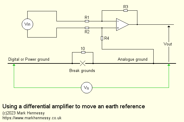
This simplified diagram shows the idea. We don't want to connect the power and signal earths at any point other than where they are originally joined on the power board - they need to be kept separate or unwanted currents will be able to flow in the earth system, which will generate voltages in the earth wiring because of the inevitable resistances. Of course, the noise voltage might be small, but so are the audio signals we're trying to amplify!
So we start by separating the earths, which breaks the loop and returns the earthing arrangements to the original design intent. But now we must accept that the two earths have a potential difference between them - represented by Vn on the diagram. The 10Ω resistor weakly ties the earths together, in case this part of the circuit has been disconnected from the rest of the unit, perhaps for testing.
Next, remember that with a differential amplifier, while it responds to the difference between its two inputs, it generates an output that is relative to the bottom end of R4. So make sure that is tied to the signal earth. Simple!
The difference between the two earths, Vn, appears equally at each input as a common-mode signal. But even a basic differential amplifier using standard 1% resistors will reject this signal by around 40dB. Remember that before, this noise was adding itself to the wanted signal, but also the loop formed was likely causing other problems, such as inducing digital noise from the Bluetooth chip into the earth (and hence the audio signal), as well as undoing the point of keeping the earths separate in the first place - meaning that class B currents from each op-amp output stage in the preamp will add to the earth noise, as would the power amps. At the very least, this would cause a large rise in distortion.
As we're switching audio signals on the pre-amp board, it doesn't make sense to retain the 4052, nor its associated 100k resistors. With that gone, we might as well lose the series caps C9 and C10. Here's what the analogue audio stages look like now:
;)
Much simpler! The 2.5V DC offset will be removed by the caps on the pre-amp board. For the analogue reference, I originally assumed I'd use a flying lead, but with the 4052 gone, we have "INL" and "INR" available, so it makes sense to use one of these.
Having ditched the 4052, we can remove R19 (the pull-up for the "INH" pin), saving 1.5mA (every little helps!). And of course, we don't need the charge pump, so let's lose that.
Here's a summary of what I removed:
- C9 and C10 - these disconnect the op-amp from the 4052
- The 4052
- 100k resistors surrounding the 4052 - R11, R12, R13, R14, R15 and R16
- The wasteful 2k2 pullup on the 4052 EN pin - R19
- Charge pump components - D1 and D2, C12 and C13, plus C11
Having removed those components, the signals were routed to the connections at the edge of the module, as shown in the diagram above, with some Kynar wire. The pads left by the 4052 are the easiest to solder to, being fairly large, so we just need to get the audio from the op-amp (pins 1 and 7) to the common of the 4052 switches (pins 3 and 13). I could have picked up the signals from the pads where C9 and C10 were, but it was easier to solder to the op-amp legs.
For the mid-point, it was just a case of picking up the connection on the 4052 pads that originally belonged to "INL" (pin 12) and joining it to the appropriate pad left by C7.
Having saved 1.5mA by removing R19, I turned my attention to R20, which is also passing 1.5mA for no obvious reason. I tried removing it, just in case the microcontroller had a weak pullup enabled (the CSR pin is open-drain), but no such luck. In fact, the module refused to connect at all with this resistor missing, which did not fit with my understanding of what the microcontroller is doing (start, send pulses to pin 40 to wake up the CSR, wait for pin 37 to go low to indicate a successful connection, send EN high, also "A" to switch over the 4052 to BT). With the resistor missing, the microcontroller sends 1 brief pulse and does nothing else, so perhaps it's expecting to see a high on pin 4 at power on, or the floating pin is confusing it. Anyway, I tried a 33k resistor, and that restored normal behaviour, and knocked another 1.4mA from the current consumption.
This saving in current isn't really about maximising battery life - 1.4mA will hardly make a serious impact there. But it does ease things for the voltage regulator supplying the module. The 3mA saved from just those two resistors reduces power consumption in the regulator by 57mW, which doesn't sound like a lot, but the thermal resistance between junction and ambient of the LP2950 is 140°C/W, so this means a reduction in junction temperature of 8°C. This also might not sound like much, but with a 24V input, we are quite close to the limits of what this regulator can do, and it is running rather warm, even with a clip-on heat sink. So for the sake of a 5 minute investigation and the replacement of one resistor, I think it was worth it. Luckily, a ⅛W resistor fits quite easily between pins 1 and 4 of the microcontroller.
This picture shows the completed modifications:
;)
Having done this, I did discover that the chip actually does makes a chime when it connects. However, this happens before the EN output goes high, so the chip isn't connected via the 4052 to the output. Removing the 4052 exposes this. However, the PIC mutes "my" 4052 until EN goes high, so this chime will also be hidden in the completed project.
Potential other mods
While this gave excellent results (more later), I could have taken this even further and removed the op-amp and surrounding resistors and capacitors. But why go to such extremes?
Firstly, the op-amp apparently takes 7mA, according to a datasheet I found here: https://pdf1.alldatasheet.net/datasheet-pdf/view/391548/PTC/PT2308.html. A TL072 takes less than half of that. If nothing else, it takes that 7mA away from the 5V regulator that supplies the module which, as discussed above, does run rather warm given that it's running with 24V at its input. An external opamp would run from the same rails as the rest of the pre-amp, and could be set to a higher gain to give if larger signal levels were needed - no worries about clipping from a single 5V rail.
As a result, we could lose the ceramic caps C1 to C4. I can't help being a bit unsure about them for audio coupling!
Also, the resistor values are rather high at 16k and 27k. The CSR is able to drive low impedance loads down to 32Ω, so we could pick values in the sub-10k region, which is the norm for low noise design.
Of course, we'd need to run a total of 4 signals from the CSR 8630 to the outside of the module, but we have provision for that - INL, INR, OUTL and OUTR.
I also considered removing the microcontroller. After all, once the 4052 had been removed, what exactly was it doing? As detailed earlier, I spent quite a bit of time investigating this, with this thought in mind.
I could easily bring out pin 37 (the "connected" signal") by simply bridging the pads belonging to pins 4 and 5 of the removed microcontroller (and ensure the firmware expects an active-low signal instead of the active-high of the current "EN" signal). But the real sticking point is the pulse(s) generated on pin 7 at power-up. These (or likely the first of them) get the CSR 8630 started up.
Ever the optimist, I did try lifting pin 7 and inserting a simple pull-up resistor between +3V3 and the pad vacated (which connects to pin 40 of the CSR). No such luck, sadly - the CSR definitely needs a pulse or three!
So if I'm determined to lose the microcontroller, I'd need to create this pulse myself. I could use the spare port on the PIC, but that would require an additional connection from it to the Bluetooth module, and that wouldn't be terribly easy to implement at this stage of the project (and wasteful if I ever change to a different module). Alternatively, I could add a simple circuit on the Bluetooth support board - there's probably space. But at this point, we really are into "why bother?" territory. Even if the microcontroller is doing almost nothing, what little it is doing is essential, and it's already there in place. So just leave it alone!
Renaming the module
This was quite an exciting prospect, especially as I was sure this won't be the last time I use one of these modules. This involves using a USB to SPI adaptor to connect to the CSR chip and updating the contents of the EEPROM - what could possibly go wrong?!
There are three main challenges here:
- Obtaining a suitable USB-SPI adaptor
- Identifying the correct SPI pins
- Finding the software
Luckily, all this is covered in this blog. At this risk of repetition, I'll cover this here, not least because websites sometimes disappear - it doesn't hurt to duplicate useful information.
For the adaptor, I searched eBay for "CSR USB-SPI", and found dozens of sellers offering something like this (note there are several variations). I figured it was worth the £15 or so to experiment.
;)
To identify the SPI pins, the details for the KRC-86B are in the Instructable. However, at a glance, you might miss them because they are in the form of an image which is hidden away in a gallery with not even a thumbnail preview. With that in mind, here's a direct link to the image. This shows us the pins on the CSR chip itself. However, the blog shows how these signals appear one the connectors on the module. I have confirmed with my module that these tally up, and my version of the schematic includes these details.
Finally, the software. Again, this is linked in the blog, but just in case, here it is: https://disk.yandex.com/d/QAdQ7zuP-X62Xg. At the time of writing, the latest version there is bluesuite.win.2.6_installer_2.6.11.1937.zip
With all of these boxes ticked, how to implement this in a way that would allow easy experimentation? As explained in the introduction, I originally expected to mount the Bluetooth module on a small piece of plywood that would be screwed to one of the aluminium side supports on the pre-amp board - the idea being to get the module up and away from the circuitry and metalwork. It would be simply wired to the preamp board with via the 6 way Molex connector. However, since then I've confirmed that I definitely need that decoupling cap across the 5V input, and that I'd be making the modifications detailed above to sort out the earthing. To facilitate this, I forgot about the plywood and used a bit of Veroboard instead (see below).
This allowed me to make a much "cleaner" connection to the Molex connector on the pre-amp, and also provides the space for connection pins for the SPI interface. As described in the blog, we need to pull the SPI_EN signal up with a 10k resistor, so I can provide for that too. In a way, this feels a bit wasteful as I'm not likely to rename it once it's been done, but I decided that we might as well make the effort, as there could be other exciting things to discover!
More details of the hardware are shown below, but with the Qualcomm Bluesuite installed and the module mounted on the Veroboard support board with the SPI connections brought out on a header, I set about connecting it up.
My USB-SPI adaptor came with a short 6 way ribbon cable with plugs for each conductor at each end. Also, there was a jumper installed in the 10 way IDC header. There was no documentation supplied with it, but I'm glad they'd plugged it in, as without it, it doesn't work. I think the idea is to connect the Vs pin to either 3V3 or 1V8, presumably to tell the adaptor what voltage to work at. Both these voltages are duplicated on pins either side, so with the jumper in place, you're still able to take the appropriate one on to your device via the ribbon cable.
Connecting up the leads was just a case of following the label on the adaptor with reference to my diagram of the support board, which obviously relies on me correctly identifying the SPI pins. And installing the SPI enable jumper. Fortunately, it worked first time!
If you plug the USB-SPI adaptor into a machine that hasn't had the Bluesuite software installed, Windows doesn't install drivers for it. For that reason, install Bluesuite first. Once plugged in and appearing correctly in Device Manager, run up "PSTool". The first time, you need to click on "SPI BCCMD" on the left, and then the adaptor should be available on the drop-down labelled "Port".
;)
Once you've clicked on "OK", the software attempts to communicate with the CSR 8630. If it fails, double-check all your connections, including the jumper that joins VS to 3V3 at the adaptor, and check also that you've taken SPI_EN high via a 10k pullup (or, in my case, installed the jumper). Click "Retry" if necessary.
It takes less than a second to populate the main window:
;)
At this point, you may wish to take the advice offered in the video in the Instructable, and back up the current config of your module. From the File menu, choose "Dump". This creates a file in the directory of your choosing that can be read with your favourite text editor. Don't ask me how to restore from the backup - I haven't explored this yet...
The list of parameters is huge, so in the filter box type "name", which will reduce the list down to just one ("Local device's "user friendly" name"). Click on that, and you'll see "KRC-86B" in the text box. Replace that with the text of your choice.
To save that to the module, simply click on "Set". Test by unplugging the USB, which powers down the module. Restart the PSTool program, and reconnect the USB and let PSTool read the config data as before. Find "name" in the list and confirm that it is what you typed earlier. And of course, you can search for it using your phone or similar. If it still appears in your list of Bluetooth devices with the old name, you might need to select it and tell your device to forget it, then re-scan.
Having got this working, I made up a dedicated lead, using a 10 way IDC header, a short length of ribbon cable, and an 8 way SIL header. I joined the 3V3 and VS leads together at the SIL header (blue and grey) because it's clearly a bit tricky to plug the IDC header and shorting plug in at the same time. So now it's very easy to hook up in future, and if I use the same header arrangment for future projects, renaming the module is practically a zero effort endeavour.
;)
Out of interest, I did take a look at the file produced from the File, Dump command above. It's a long list of values, as you'd expect. Searching for "name" gets us this:
  // PSKEY_DEVICE_NAME
  &0108 = 524b 2d43 3638 0042
Converting those hex pairs to ASCII gets us this:
RK-C68B
And swapping pairs around:
KRC-86B
Repeating the process after renaming the module:
  // PSKEY_DEVICE_NAME
  &0108 = 614d 6b72 7327 4220 756c 7465 6f6f 6874 5320 6570 6b61 7265

  aMkrs'B ulteoohtS epkare

  Mark's Bluetooth Speaker
You'll notice that when filtering for the name in PSTool, this value is shown just above the buttons on the right of the window:
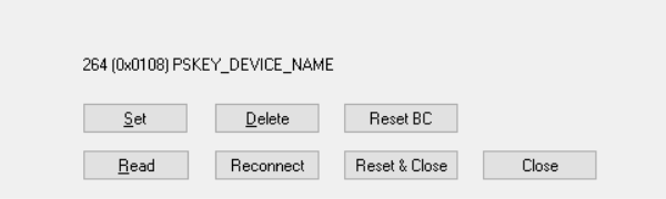
Where 108 (hex) is perhaps the address in memory where this is stored or, given that some of the parameters can be variable length (like this one) or some of them take more space than others, it's more likely that this is the number of the parameter - the actual storage is managed at a lower level.
Just in case it might be of use to someone experimenting with this module, here is a copy of my backup. I can't guarantee it'll work in other modules or even other versions of this one, and as mentioned, I haven't yet tried to work out how you might restore a backup to the module.
Implementing the modified KRC-86B in this project
Finally - or is it? - this is how we installed the module in the unit.
As mentioned above, I planned to hold the Bluetooth module away from the circuitry with a bit of plywood, but changed to Veroboard in light of what was I discovered during this investigation. This holds the decoupling cap, the capacitor to reference the audio ground, and the SPI interface:
;)
The supplied decoupling cap was 470uF - although I did spot a YouTube video that mentioned that they'd received a 100µF, so I guess there's a bit of variation. However, it had quite a high ESR (0.48Ω), so to give myself the best chance of minimising digital noise, I used a 220µF that had a much lower ESR of 0.04Ω (Rubicon ZLH).
Remember that the module has its connections spaced at 2mm rather than the much more convenient 2.54mm. But as we're only using 11 out of the 15 connections to the module (plus the EN connection on the side), the resulting Veroboard was pretty much the same width as the module. I used 0.7mm solid core wire to join the module to the Veroboard, and these simply bent into the required pitch. I did think I'd need to use double-sided adhesive foam to attach the module to the board, but the connection wires resulted in a perfectly stable construction which I think will hold up over time.
;)
Upon first test, I was rewarded with absolute silence. In a good way! All my previous tests were complete with nasty digital noise at varying levels. The decoupling cap made a useful improvement, as did my crude tests with the mid-point (literally touching a 47µF cap to C7 - the other end connected to signal ground), but with C7 and C8 still in circuit, this was not a proper test. But with all the mods done and the module mounted on this simple support board, the results are extremely good indeed. Using my bench amp, I heard nothing but white noise at full volume. This speaker has a sensitivity of around 30mV, which is about 20dB more sensitive than this system, so I doubt I'll have any noise worries.
I'm assuming the bulk of the white noise will be as a result of the resistors surrounding the op-amp (16k and 27k). As mentioned above, if removing the op-amp to use an external diff-amp, these resistors could be usefully reduced in value to minimise thermal noise. So that's another reason to consider the extreme mods.
The average current consumption has fallen from around 30mA to 25mA. We know that removing R19 and R20 acounts for 3mA of that. The clip-on heat sink on the voltage regulator is noticeably cooler now, sitting at about 40°C on the bench (it was more like 50°C before the mods). Obviously the junction will be hotter, and the temperatures will rise when it's all in the case, but it's definitely a step in the right direction. But that op-amp taking 7mA is annoying though!
I changed my mind! Here's what actually happened...
OK, I couldn't help myself!
The more I thought about the 7mA taken by that op-amp, and how much it was loading up the 5V regulator, the more uncomfortable I was. Yes, it was probably OK, but it just didn't sit right with me.
The first step was to confirm what the datasheet said. I carefully lifted pin 8 and soldered a short length of fine wire to it, then hooked up a multimeter in series with 5V, and yes, it does take 7mA. 7.77mA, to be precise.
With 19V dropped across the LP2950 and an average current of 25mA, it dissipates 475mW. Of that, nearly 150mW is because of the op-amp. Remembering that the thermal resistance (junction to case) is 140°C/W, that 150mW accounts for a temperature rise of 21°C.
You might be wondering why I don't just drop the input voltage to the regulator? That would just be a case of increasing the 10Ω series resistor. A 330Ω resistor, for example, would drop 8.25V. It will dissipate 200mW, leaving 275mW in the regulator. But that heat has to go somewhere. And that resistor is right next to the regulator on the board, so will be sharing its warmth with that.
Whereas if we remove the op-amp, the regulator dissipates something like 325mW. And the replacement - a TL072 - only takes 2.8mA. Overall, that's a saving of 5mA. And that's on top of the 3mA we saved from the module by removing R19 and R20. All steps in the right direction...
But before we go any further, what about the work done so far? Well, as mentioned, this won't be the last project I do using these modules. The next one is a much smaller, simpler project which will run from 12V DC. That will result in a much happier 5V regulator.
So on the assumption I'm keeping the above support board and module to use in a future project, it doesn't feel like wasted effort (not that it matters - this is a hobby after all!). With that decided, I set about designing a new support board with enough space to accommodate a differential amplifier.
We need to run 15V to the board for the op-amp. Looking at the 6 way Molex connector on the pre-amp board, there is space to change it for a 7 way, and the next available track already has 15V on it. So without a shadow of doubt, it was meant to be!
I removed almost everything from the spare module - all the components listed above, including the 4052 and associated components, the charge pump, etc. Then the op-amp and associated passives. Four short lengths of Kynar wire were added to link from pads left by the 4052, which get us to the pads at the edge of the module. The other ends of those wires pick up the audio from the pads vacated by C1 to C4. Finally, R20, replaced with a 33k, soldered between pins 1 and 4 of the microcontroller.
;)
A quick test showed that the current consumption was down to about 17mA when connected and playing music, which is in line with what we'd expect - before we were around 25mA, and the op-amp took nearly 8mA. But there was one pleasant surprise: no digital noise, despite the temporary lash-up involving long test leads and no decoupling capacitor. This suggests that the original op-amp circuit was picking up noise somewhow - perhaps via a bad grounding strategy. That's impossible to verfify without removing all of silk screen to inspect the layout.
About 5 or 6 seconds after stopping playback, the module goes get quite noisy. Checking, the DC potential on the outputs drops from around 0.8V to 0V. It looks like the output stage is being turned off to save power, and goes to a high impedance state - so the noise is just pickup. Will that be a problem? Probably not, but it's something to keep in mind. Worst-case, a low value resistor added between hot and cold would fix it. Also, I will need to make sure this does not result in pops and clicks from the diff-amp when built, as the EN line stays high while this happens.
Interestingly, while that happens with my phone, it doesn't with my Windows 10 laptop. Obviously a power saving measure, but easily missed if you don't test with a range of source devices.
I did discover that to put the module in that connected-but-low-power state with the laptop, you have to switch the audio output device (from the menu you get when you pop up the volume control from the system tray) away from the Bluetooth module.
When in this power-saving state, the current draw is a bit variable, with occasional narrow peaks, but the average current demand is tiny - just a couple of milliamps.
As this basic testing showed that all was working as expected with the module after its mods, it was time to finalise the layout for the support board. This time I decided to mount the module vertically by threading the wires through the holes in the module and soldering both sides to adjacent holes in the Veroboard. This took less space, but is perfectly robust and the aerial is still well away from the electronics and metalwork.
Initially I planned to include a couple of transistors to switch the op-amp on and off according to the state of the incoming 5V rail. Although we are generally aiming to minimise the current consumption down wherever we see an opportunity, we're perhaps not terribly worried about 2.8mA - remember, the point of this mod was to get that 7mA away from the 5V regulator. But there was space on the board to do it, so for the sake of 2 transistors and 4 resistors, it made sense.
But upon reflection, I decided to simplify. Why run both 5V and 15V to the module, then separately switch the 15V rail when the 5V rail was already being switched? Instead, I moved the 5V regulator from the pre-amp board to the support board. Now, when the PIC turns on the Bluetooth supply, 24V arrives at this board, where it meets the relocated regulator. At the same time, the op-amp is powered from this rail, suitably decoupled. Yes, it's higher than 15V, but well within the limits of a TL072. We only picked 15V for the pre-amp because of the 4052.
Plus, moving the regulator away from the crowded pre-amp board to the vertically-mounted support board massively improves the airflow around it. Win-win!
Turning to the amplifier, the gain of the unmodified module is x1.69 (27k/16k), and as the output voltage was measured at 0.83VRMS for a 0dBFS signal, this implies the differential output voltage at the CSR 8630 is 0.49V. I'm calling that 0.5V! But just to be sure, I re-tested this on the raw module during the above testing, and it measures 0.535V. Close enough!
As we have complete freedom now, what should we pick? CD players produce 2VRMS for 0dBFS, but who uses those these days? It's more likely that a headphone output would feed into one of the line inputs and those are a bit variable in their voltage.
As an inital compromise, it made sense to go for around x2, giving 1V. This is what you get from an iPhone headphone socket (if you have an old model) or via the £9 Lightning-to-3.5mm adaptor if you have a newer phone. This means simple resistor values - perhaps 3k3 and 6k8. We could go lower as the CSR 8630 can drive headphones, but these are a decent starting point.
But the components around the op-amp need to have a low profile to avoid clashing with existing parts on the pre-amp board. So that means using ⅛W resistors that can lie down on the board, rather than ¼W resistors that would need to stand up. Checking my stores, I had just enough ⅛W 3k3 1% resistors but no 6k8. But I did have plenty of 7k5. That'll do for now! So the gain is x2.27, resulting in 1.216VRMS, in theory. That's about +4dBu. I'm sure it'll be fine, but we can always revisit this in future...
While low is good for minimising thermal noise, we need to consider the coupling capacitors - the lower you go, the larger they need to be. With resistors of 3k3 and 7k5, what impedance would each capacitor see? For the non-inverting input, that's simple - it's the sum of the two reistors used (10k8). How about the inverting input? The inverting input is a virtual earth, so the impedance is just 3k3, right?
Wrong! But it's a common misconception. I've written a separate article looking at this, but suffice to say, it's just under 2k. Given that, 10µF is fine for this system, but I would go higher if this was hi-fi - it's well known that electrolytic capacitors exhibit a rise in distortion when signal voltages develop across them.
As for choosing values for the mid-point generator, that was covered earlier.
Here is the complete design:
;)
This time I made a slight change to the SPI enable jumper - moving it across to enable the interface also disconnects the CSR 8630 from the 5V regulator. This means there's no need to disconnect the Bluetooth support board from the pre-amp board, and no worries about "backfeeding" the regulator. This is less of a problem for the first version because that uses pin headers rather than a latching Molex KK header which grips rather tenaciously...
Here's a picture of the V2 support board, complete with the modified Bluetooth module:
;)
This side view gives a better view of how the module is attached to the board, using 0.7mm tinned copper wire. The resulting assembly is very strong, and I'm sure it'll prove to be reliable. I did add a few drops of Superglue to help secure the Kynar wire.
;)
This works very well. It only takes about 20mA from 24V, and the voltage regulator is running at a perfectly comfortable temperature, even without the clip on heatsink that was very necessary before. Compared to the first version, there is much less white noise now, and the higher output voltage also works to improve the signal to noise ratio. It is well-behaved, with no audible clicks when switching in to or out of low power mode, and nothing but silence when in that state. Although it was extra work, I'm glad I did it. I wouldn't have been comfortable knowing that I could have improved on my first effort. But that unit will be absolutely fine for the smaller project I have in mind, so building that was not in vain.
You might notice that there is a small tantalum capacitor on the input to the 5V regulator and a 100Ω series resistor, yet the schematic above shows 47µ and 10Ω respectively. Those changes happened after the photos were taken, at the final stages of development, when I discovered that there were some audible noises from the Bluetooth module. These were not on the audio output of the module, as the noises didn't change in level with the volume control, and stayed the same even with another input selected, until the PIC turned off the Bluetooth module (after a delay for convenience).
The noises were caused by the CSR8630 drawing current in large spikes; while the average current might be around 17mA, the peaks are more like 80-100mA. This caused large disturbances to be present at the input to the voltage regulator as the switching transistor came out of saturation - the voltage at this point was dropping by around 10V! This was finding its way into the audio path elsewhere in the unit, albeit at a relative low level thanks to the careful earth design and the decent CMRR of the op-amps. Upping the base drive to the switching transistor helped, as did swapping to another with a higher hFE and current rating (just in case!), but increasing the capacitor to 47µ reduced the power supply disturbances to less than half a volt. Careful testing with my workshop speaker showed that while this signal could still be found on supply rails and the power ground, it was not present at the speaker outputs. Even with that speaker set to maximum gain (around 40dB), there was nothing but white noise at the speaker outputs of each of the power amplifiers.
Finally, it's worth mentioning that TL072s take a bit more current than the datasheet says. Rather than 2.8mA, it's more like 4mA. To be fair, they say that 2.8mA is "typical", and it might be as high as 5mA. I did try many different samples from different manufacturers and different vintages, but saw no real change. If that was a real problem, there's always the TL062, but that has more distortion. And it's still better than the NE5532 or OPA2134, both of which take 8mA.